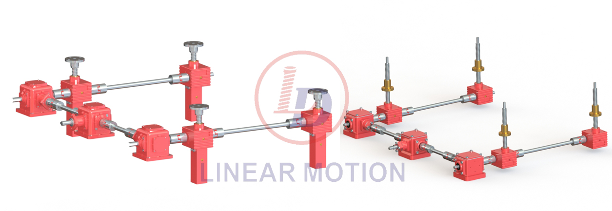
What are the two basic transmission types of screw jacks?
There are two types of basic transmission forms of screw jacks.

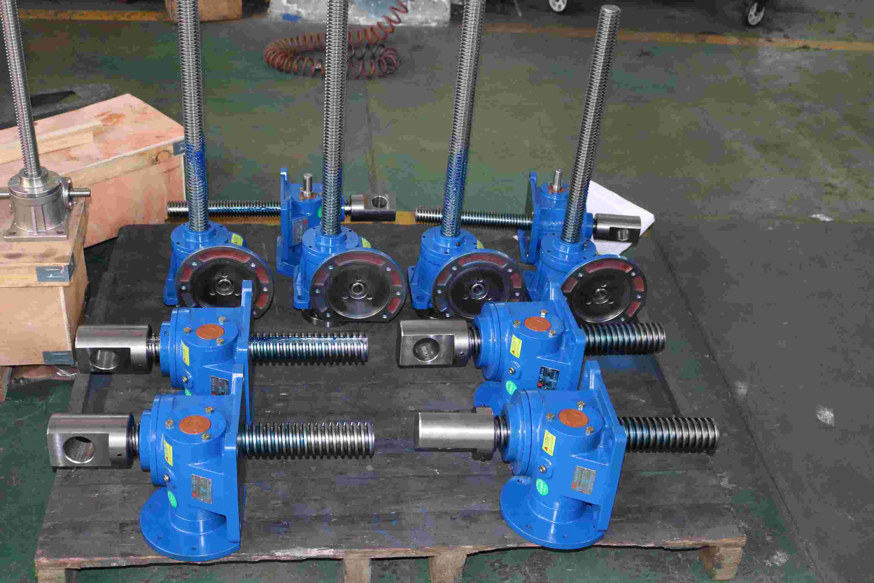
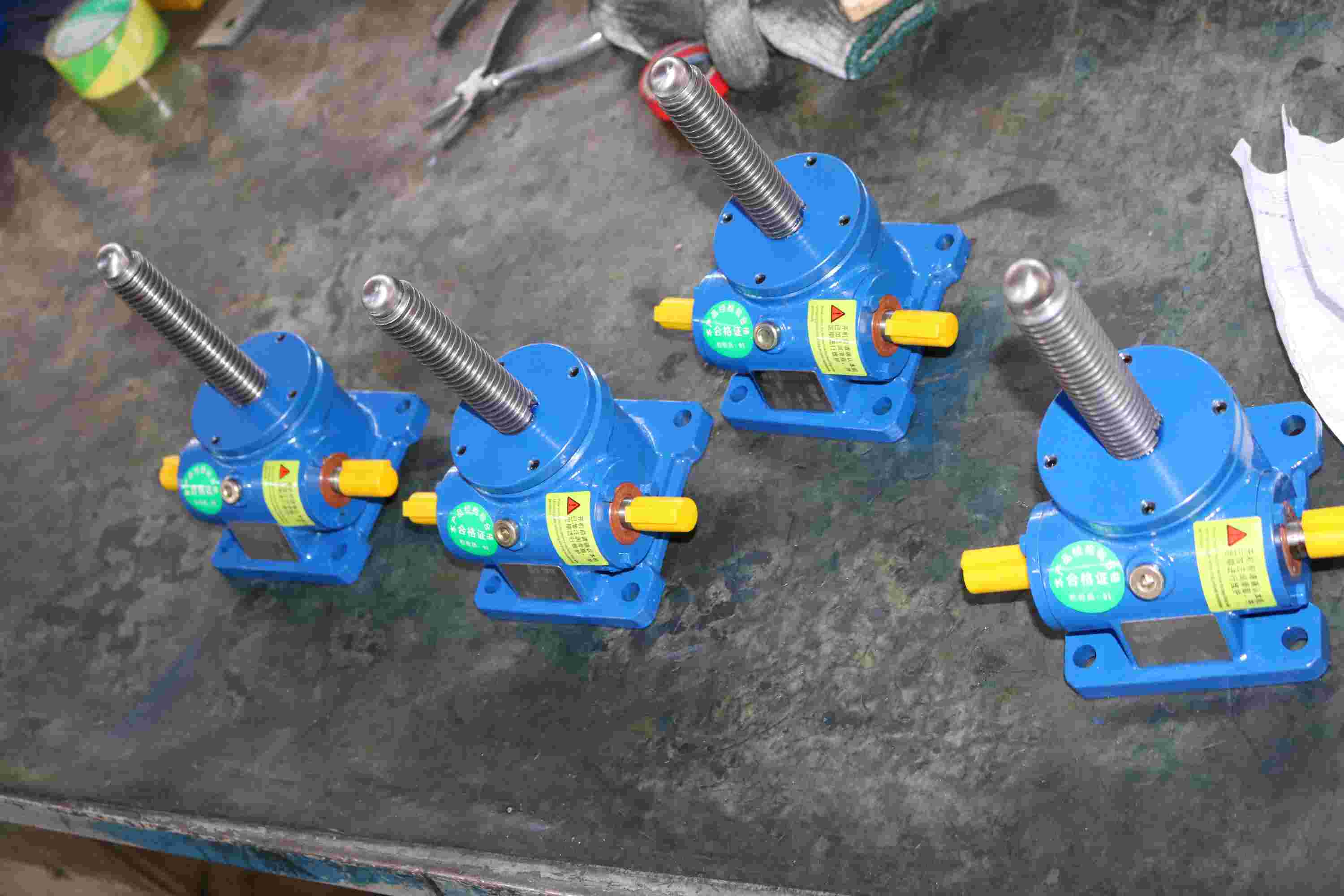
1.Nut Movement
In Brief: When the worm shaft is rotated the lead screw rotates in the body of the screw jack at the same rate as the worm gear. The nut on the lead screw moves in a linear direction along the screw when fixed to a structure that prevents it from rotating with the screw. This design is also available with a “Safety Nut”.
In Detail: When a screw jack unit is operated, the rotation of the worm shaft causes the worm gear to rotate. For rotating screw jacks the lead screw is fixed to the worm gear and they rotate at the same speed. As the worm gear turns, the friction forces on the screw thread act to turn the nut also. The greater the load on the screw jack unit, the greater the tendency of the nut to turn. It is obvious that if the nut turns with the screw, it will not raise the load. Therefore the nut needs to be fixed to a structure to prevent rotation.

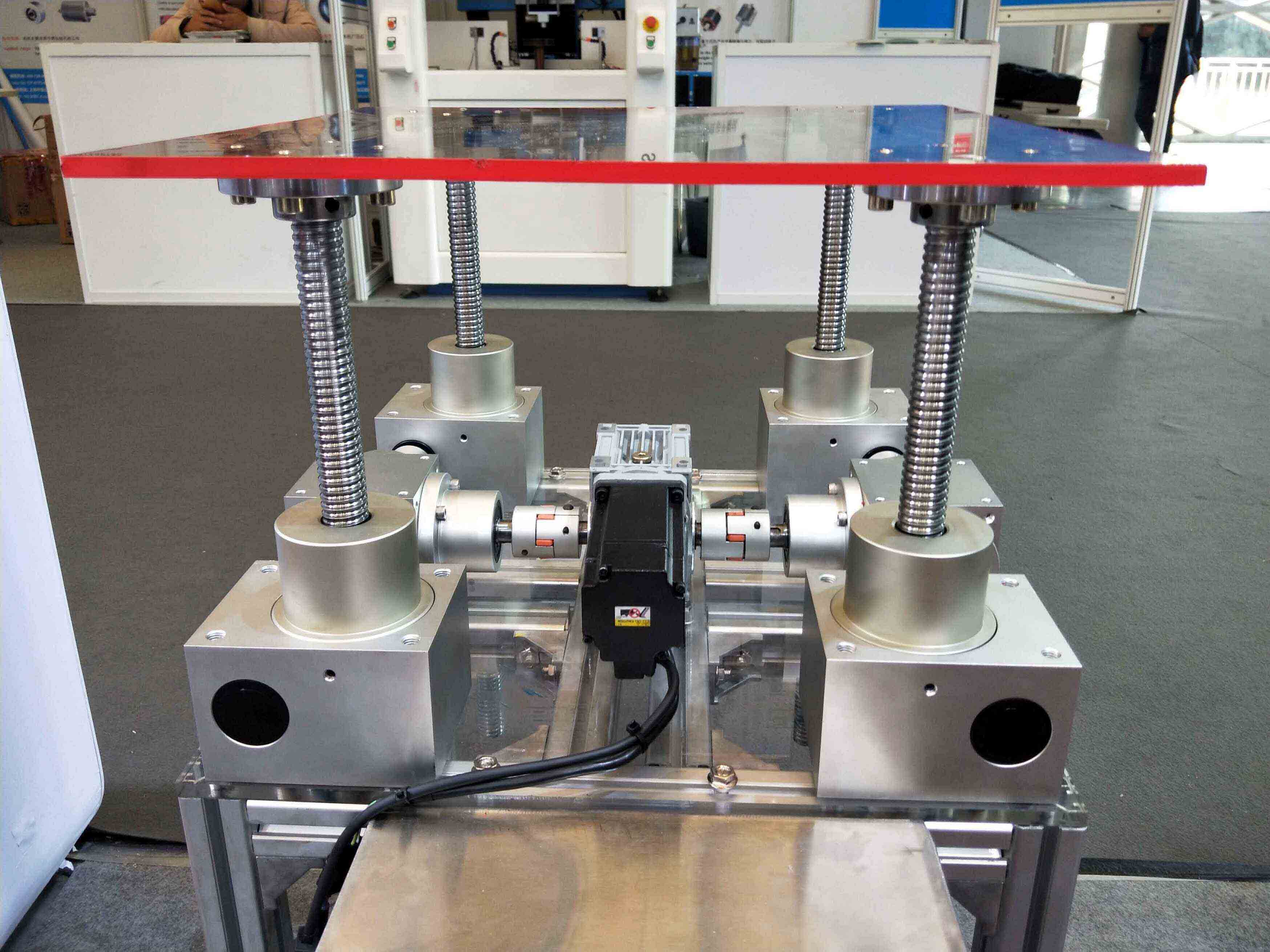
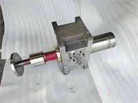
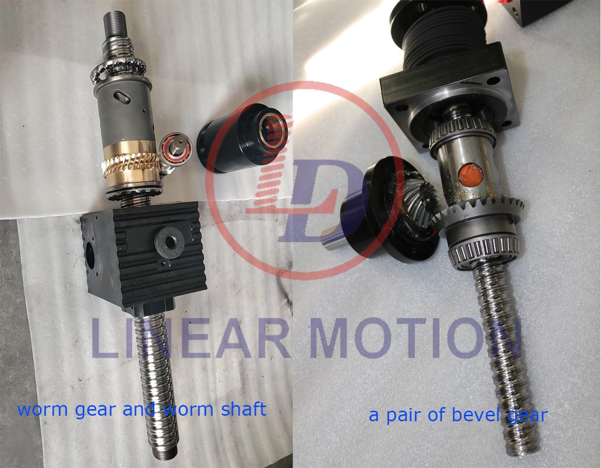
2.Screw Movement
In Brief: The lead screw translates through the body of the screw jack when the lead screw is prevented from rotating with the worm gear. This is typically done by fixing the end of the lead screw to the structure that needs to be moved linearly.
In Detail: When a screw jack unit is operated, the rotation of the worm shaft causes the worm gear to rotate. For translating screw jacks the worm gear is threaded to accommodate the lead screw thread. As the worm gear turns, the friction forces on the screw thread act to turn the screw also. The greater the load on the screw jack unit, the greater the tendency of the screw to turn. It is obvious that if the screw turns with the nut (worm gear), it will not raise the load. In those cases where a single unit is used, and where the load cannot be restrained from turning, it is necessary to screw jack with an anti-rotation mechanism (keyed screw jack).