Total Cost of Ownership (TCO) Dry-Type vs. Oil-Immersed Transformers

Today I'm going to introduce a very important concept to all readers:

TOC about Dry-Type Transformer vs. Oil-Immersed Transformer.

1. WHAT IS TCO?

First let's clarify the Core Components of TCO (Not Just Purchase Price)

TCO = Initial Procurement Cost + Installation & Civil Construction Cost + Operating Loss Cost + Maintenance Cost + Compliance & Insurance Cost + Residual Value / Disposal Cost + Hidden Downtime Risk Cost

This is the key logic when comparing dry-type and oil-immersed transformers.
Many customers only look at the equipment price, ignoring long-term copper and iron losses, civil/fire protection costs, O&M, and fire risks.


2. Key TCO Differences: Item-by-Item Comparison

a. Initial Procurement Cost (CAPEX)

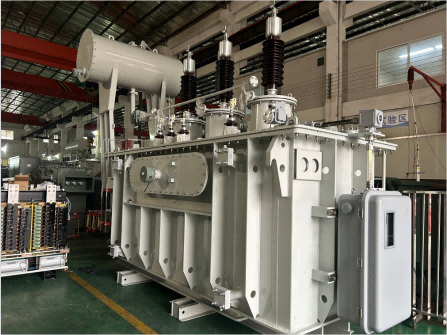
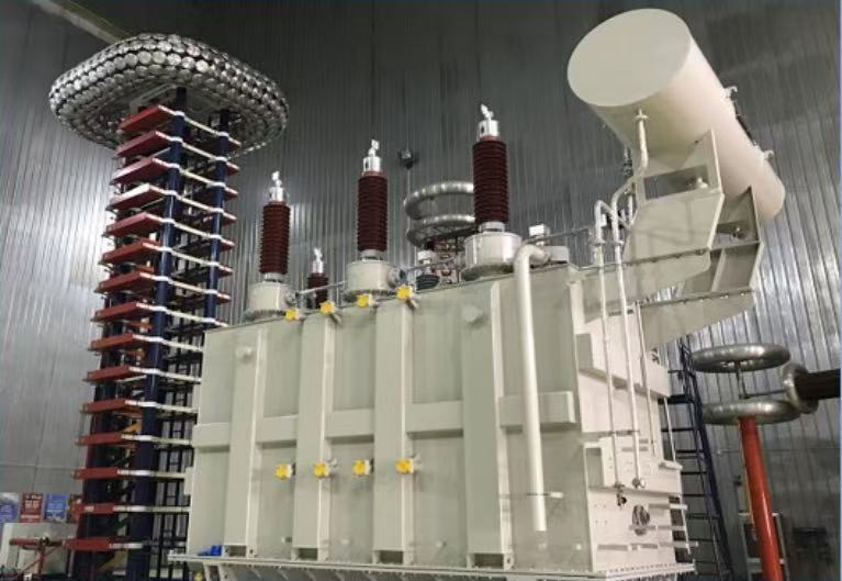
Oil-Immersed (Liquid-Filled):

For the same capacity and voltage level, lower unit price. Mature silicon steel and winding design gives strong economies of scale.

Dry-Type:
Epoxy resin cast or open-type structure, higher material and process cost, significantly higher upfront equipment price.

b. Installation, Civil Works & Supporting Infrastructure

Oil-Immersed:
Requires oil containment pit, firewalls, oil drainage pit, fire suppression system, independent transformer room or outdoor fencing.
→ High civil, fire protection, and anti-leakage investment, larger footprint.

Dry-Type:
No oil, no explosion protection, minimal fire protection requirements.
Can be installed indoors (distribution rooms, floors, basements) without oil pits or fire compartments.
→ Significantly lower civil costs and smaller footprint.

c. Operating Loss Cost (Largest TCO Component, Most Critical Long-Term)

No-load and load losses are similar, but dry-type has slightly poorer heat dissipation, leading to higher temperature rise under the same load.

Oil-filled units have better cooling and overload capability → slightly better long-term efficiency under full load.

TCO must be calculated based on 20–30 years of energy loss cost.
Differences are more pronounced under low-load or standby conditions.

d. Maintenance Cost (OPEX)

Oil-Immersed:
Requires regular oil testing, filtration, refilling, leak inspection, bushing cleaning, cooling fan maintenance.
→ Higher maintenance frequency and ongoing labor/material costs.

Dry-Type:
Almost maintenance-free. Only basic dust cleaning and insulation checks.
No oil handling or leakage risks → very low lifecycle O&M cost.

e. Safety, Compliance & Hidden Risk Costs

Oil-Immersed:
Uses flammable insulating oil → fire risk, leakage pollution, environmental compliance issues.
Restricted in high-rise buildings, malls, hospitals, and underground spaces.
High fire inspection cost and potentially huge downtime losses in case of fire.

Dry-Type:
Flame-retardant or non-flammable, no oil leakage, environmentally friendly.
Suitable for indoor, high-rise, underground, explosion-proof, and densely populated areas.
→ Near-zero hidden costs related to fire, environmental penalties, or downtime.

f. Lifespan, Residual Value & Disposal Cost

Oil-Immersed:
Lifespan 25–30 years. Transformer oil, core, and windings have high recycling value.
However, disposal requires professional oil treatment → environmental cost.

Dry-Type:
Lifespan 20–30 years. No oil disposal required.
Epoxy windings have slightly lower recycling value.


3. Selection Conclusion 

When Oil-Immersed Has Better TCO?

Outdoor substations or industrial parks with ample space and no strict fire restrictions;

Large capacity, high-load, long-term operation → benefit from lower upfront cost and better cooling;

Sufficient land and acceptable civil/fire investment, less concern about maintenance labor.

When Dry-Type Has Better TCO?

High-rise buildings, malls, hospitals, subways, basements, and densely populated areas;

Explosion-proof, chemical plants, cleanrooms, environmentally strict facilities;

Avoid high civil/fire investment, prefer low maintenance and reduced fire/environmental risk;

Although higher upfront cost, over 20 years the savings in civil works, O&M, and risk far exceed the price difference → lower total TCO.


4. Standard Approach to Building a TCO Report (Template Logic)

a. Set unified assumptions: same capacity, voltage, loss class, service life (20/30 years), and electricity price.

b. Break down costs: equipment cost, civil/fire cost, annual energy loss cost, annual maintenance, risk premium, residual value.

c. Apply discounted lifecycle cost calculation and determine payback period(How many years it takes to recover the higher dry-type cost through savings in energy, O&M, and civil works).

What is Transformer?

Transformer is an electrical device that uses the principle of electromagnetic induction to change alternating current voltage.


Its core structure consists of two sets of coils wound around a closed iron core. When alternating current is applied to the primary coil, an alternating magnetic field is generated in the iron core, which in turn induces an alternating voltage in the secondary coil. The voltage change depends on the turns ratio of the two coils. If the secondary coil has more turns than the primary coil, the output voltage will increase, which is called a step-up transformer; otherwise, it is a step-down transformer.


A transformer's main structure consists of three parts:

Core: Typically made of laminated silicon steel sheets, forming a closed magnetic circuit. Its function is to efficiently conduct and confine the magnetic field.

Primary Coil (Side): The winding connected to the input power supply.

Secondary Coil (Side): The winding that outputs the required voltage.

Key Characteristics and Parameters

  • Rated Capacity: The maximum apparent output power that enables the transformer to operate safely for extended periods, measured in kilovolt-amperes (kVA).
  • Rated Voltage: The primary and secondary operating voltages specified during design.
  • Efficiency: The ratio of output power to input power. Modern large transformers can achieve efficiencies exceeding 99%, with losses primarily originating from copper and iron losses.
  • Impedance voltage: An important technical parameter that affects the magnitude of short-circuit current and voltage regulation rate.


Simply put, transformers cleverly achieve the raising and lowering of AC voltage through the process of "electricity generating magnetism, and magnetism generating electricity," making them an indispensable basic component in modern power systems and almost all electronic equipment.

The Significance of Lamination in Transformer Cores

Transformers are essential electrical devices that facilitate the efficient transmission and distribution of electrical energy. At the heart of every transformer lies its core, which plays a crucial role in transforming voltage levels. One commonly employed technique in constructing transformer cores is lamination. In this article, we will explore why lamination is used and delve into its significance in the design and performance of transformer cores.

 Why COGO Lamination?

The primary reason for incorporating CRGO laminations in transformer cores is to mitigate energy losses caused by magnetic characteristics while maintaining optimal performance. Laminated cores consist of numerous thin layers of a magnetic material, typically silicon steel, stacked together and insulated from each other. This technique introduces several benefits that enhance the efficiency and reliability of transformers.


Reducing Eddy Current Losses:

When an alternating current flows through the primary winding of a transformer, it induces a magnetic field in the core. However, this varying magnetic field can induce small circulating currents, known as eddy currents, within the solid core material. These eddy currents generate heat and consume a significant amount of energy, leading to undesirable energy losses. Lamination effectively addresses this issue by breaking up the solid core into thin insulated layers, thus interrupting the flow of eddy currents and minimizing energy dissipation as a result.


Controlling Magnetic Flux:

Lamination also helps in controlling the flow of magnetic flux within the transformer core. By dividing the core into multiple layers, each with its own magnetic path, laminations ensure that the magnetic flux follows a desired and efficient route. This controlled flux path minimizes magnetic leakage and maximizes the coupling between the primary and secondary windings, leading to improved transformer performance.


Reducing Hysteresis Losses:

Hysteresis loss occurs when the magnetic field within the core material repeatedly reverses its polarity with each alternating cycle. By using laminations, the size of the hysteresis loop, and thus the associated hysteresis losses, can be significantly reduced. This is achieved by carefully selecting the thickness and composition of the laminations, optimizing the magnetic properties and reducing energy losses within the core.

SO…

Lamination is a fundamental technique employed in transformer core design to enhance efficiency and reduce energy losses. By effectively controlling eddy currents, magnetic flux, and hysteresis losses, laminated transformer cores ensure optimal performance and improve the overall energy efficiency of electrical power distribution systems. As technologies continue to advance, the use of advanced laminated materials and designs will further contribute to the evolution of efficient and sustainable transformers.

Understanding Different Grades of Oriented Silicon Steel for Transformer Cores

Oriented silicon steel, also known as electrical or CRGO (Cold-Rolled Grain-Oriented) silicon steel, is a vital material used in the manufacturing of transformer cores. Its unique magnetic properties and grain orientation make it an excellent for efficient power transmission. In this article, we will explore the various grades of oriented silicon steel and their applications in the transformer industry, including the addition of the M4 grade. We are proud to inform you that SHUNGE possesses a wide range of oriented silicon steel grades; please contact us for any specific requirements.

Oriented silicon steel

1. M0 Grade:

M0 grade oriented silicon steel is highly regarded for its exceptional magnetic characteristics. With its low core losses and high magnetic permeability, it is ideal for use in high-efficiency power transformers. The superior energy efficiency and improved voltage regulation provided by M0 grade contribute to enhanced performance in diverse applications, ranging from industrial power distribution to renewable energy systems.

2. M1 Grade:

M1 grade oriented silicon steel exhibits excellent magnetic properties and finds common usage in medium to high-power transformers. It offers slightly higher core losses compared to the M0 grade but remains a highly reliable and efficient option. Transformers utilizing M1 grade silicon steel serve various electrical systems, including utility substations, commercial buildings, and manufacturing facilities.

3. M2 Grade:

M2 grade oriented silicon steel is specifically designed for applications requiring lower magnetic flux density. Although it has higher core losses compared to M0 and M1 grades, it remains suitable for transformers where efficiency is not the primary concern. M2 grade silicon steel is commonly used in low-power transformers, such as those found in household appliances and lighting systems.

4. M4 Grade:

The M4 grade oriented silicon steel is a specialized grade that offers distinct magnetic properties and is suitable for specific transformer applications. While providing unique benefits, such as lower core losses at higher frequencies, it caters to transformers operating in demanding environments. M4 grade silicon steel is widely used in power electronics, renewable energy systems, and high-frequency transformers.

CRGO silicon steel

Oriented silicon steel, with its grain orientation and superior magnetic properties, plays a crucial role in ensuring the efficiency and reliability of transformer cores. By understanding the different grades available, manufacturers can select the most suitable material for their specific power transmission needs. Whether it is the widely used M0 and M1 grades, the specialized M2 grade, or the advanced M4 grade, each offers unique benefits and applications, contributing to the seamless functioning of electrical systems worldwide. At ShunGe, we are proud to offer a wide range of oriented silicon steel grades, including nearly all available grades. Please feel free to contact us for any specific requirements or inquiries.

CRGO Silicon Steel for Efficient Power Transmission

Transformer core plays a crucial role in the efficient and reliable transmission of electrical power. As a key component, it provides a low reluctance path for the magnetic flux generated by the primary winding to be transferred to the secondary winding. Among various materials used for transformer cores, oriented silicon steel, also known as CRGO (Cold-Rolled Grain-Oriented) silicon steel or electrical steel, stands out for its exceptional magnetic properties and widespread application in different power ratings of transformers.

CRGO Silicon Steel: A Superior Core Material:

CRGO silicon steel is specifically engineered to exhibit grain orientation, enabling it to maximize its magnetic properties when subjected to an alternating magnetic field. The manufacturing process involves a controlled cold rolling technique that aligns the crystal grains within the steel in a specific direction. This grain orientation reduces the occurrence of magnetic domains and minimizes hysteresis losses and eddy current losses, making CRGO silicon steel the preferred choice for transformer cores.

Applications in Different Power Ratings:

  1. Low-Power Transformers:
    In low-power transformers, such as those used in residential and small-scale commercial applications, CRGO silicon steel is utilized to enhance energy efficiency. The material's low core losses and high magnetic permeability contribute to reduced power wastage and improved voltage regulation, ensuring optimum performance in household appliances, lighting systems, and electronic devices.

  2. Medium-Power Transformers:
    Medium-power transformers, commonly employed in industrial settings and power distribution networks, require reliable and efficient core materials. CRGO silicon steel offers excellent magnetic properties at intermediate power ratings, enabling enhanced energy transmission and minimal power losses. These transformers find application in areas such as manufacturing facilities, commercial buildings, and utility substations.

  3. High-Power Transformers:
    For high-power transformers, such as those used in large-scale power generation and transmission systems, CRGO silicon steel provides superior performance. With its advanced grain orientation and optimized magnetic characteristics, it minimizes core losses and enhances efficiency, ensuring reliable power transmission over long distances. These high-power transformers are crucial components of electrical grids, enabling the efficient distribution of electricity to cities, industries, and infrastructure projects.


The selection of the core material plays a vital role in the performance and efficiency of transformers. CRGO silicon steel, also known as oriented silicon steel or electrical steel, stands out as an ideal choice for transformer cores across different power ratings. Its unique grain orientation and magnetic properties significantly reduce energy losses, ensuring optimal power transmission. Whether in low-power, medium-power, or high-power transformers, CRGO silicon steel demonstrates its superiority in enhancing efficiency and reliability in the transmission and distribution of electrical energy.

Why is lamination used in the core of a transformer?

Transformers are electrical devices that transfer electrical energy between two or more circuits through electromagnetic induction. Transformers consist of two main components: a primary winding and a secondary winding, both wound around a core.

The transformer core of a transformer plays a crucial role in its efficient operation. It is typically made using laminations or stacked layers of a magnetic material, such as silicon steel. But why is lamination used in the core of a transformer? Let's delve deeper into this question.

The primary reason for using laminations in the transformer core is to minimize energy losses. When an alternating current (AC) flows through a transformer, the magnetic field generated by the current causes the core to undergo rapid magnetization and demagnetization cycles. These cycles lead to two types of energy losses in the transformer core: hysteresis loss and eddy current loss.

Hysteresis loss occurs due to the repeated flipping of magnetic domains within the core material, resulting in energy dissipation in the form of heat. Laminating the core helps to reduce this loss by segmenting the core into thin layers. These layers disrupt the continuous path for magnetic flux, reducing the area enclosed by the hysteresis loop and thus minimizing hysteresis loss.

Eddy current loss, on the other hand, is caused by the circulating currents induced within the core material due to the varying magnetic field. By using laminations, the transformer core is effectively divided into isolated pieces, reducing the continuous loops that the eddy currents can flow through. This segmentation significantly decreases the cross-sectional area available for eddy currents and, consequently, reduces eddy current losses.

Moreover, laminations also enhance the mechanical strength and stability of the transformer core. By stacking and tightly clamping the laminations together, the core becomes more rigid and less susceptible to mechanical stresses and vibrations. This ensures that the core maintains its integrity and optimal magnetic properties throughout the transformer's operation.

In summary, the use of laminations in the core of a transformer is essential for minimizing energy losses, particularly hysteresis and eddy current losses. By dividing the core into thin layers, laminations reduce the path for magnetic flux and circulating currents, resulting in improved efficiency and overall performance of the transformer. Additionally, laminations enhance the mechanical stability of the core. These factors collectively contribute to the reliable and efficient operation of transformers in applications.

Unveiling the Magnetic Marvel The Fascinating World of Orientation Silicon Steel

In the realm of materials science, there exists a star that shines brightly in the field of electrical engineering – orientation silicon steel, or simply, oriented silicon steel. This isn't just any ordinary metal; it's a technological wonder that revolutionizes the way we think about electricity and magnetism.

Imagine a material so refined and engineered that it exhibits exceptional magnetic properties, making it the go-to choice for transformers and other electrical devices. Oriented electrical steel undergoes a complex manufacturing process involving rolling and annealing to align its magnetic domains in a specific direction. This alignment is crucial, as it significantly reduces energy loss during the transformation of electrical energy, enhancing efficiency by leaps and bounds.

Orientation Silicon Steel

But why should we care? Well, in today's world where sustainability and energy efficiency are paramount, every little bit of energy saved counts. Transformers equipped with orientation silicon steel play a pivotal role in reducing electricity wastage, thereby contributing to greener, more eco-friendly power grids.

Moreover, the material's thin gauge and high permeability allow for more compact transformer designs, making it an invaluable asset in the ever-shrinking world of electronics. From large-scale power stations to the tiny transformers inside our gadgets, orientation silicon steel is there, silently working its magic.Orientation Silicon Steel

So, the next time you marvel at the seamless flow of electricity that powers your life, remember the unsung hero behind the scenes – orientation silicon steel. It's a material that's not just about steel; it's about innovation, efficiency, and a brighter, more sustainable future.

Why use cores in transformers?

Transformers often require/use iron cores because they operate on magnetic forces, which are difficult to understand when sharing certain characteristics with good old "electricity" (ohms, volts, amperes, etc.). Let's try some simplified ways to get the overall idea.

Start with a screwdriver - just a cylindrical coil. If we let the current flow through, a magnetic field (we call it the H field) is formed. The field depicted with the imagined field line flows up through the center of the coil, then disperses again after leaving the cylinder, then reassesses and re-enters the other end. You've seen the picture in the textbook. The magnetic field is strong and contained inside the cylinder (ID), while the magnetic field strength is weak outside (OD) because it diffuses in space. If the H magnetic field interacts with "anything" around the coil, whether it is vacuum, air or iron, it produces what we call a B magnetic induction field within the "material", the strength of which depends on the strength of the magnetic field. The properties of "matter" are called "permeability". For a given magnetic field strength H, vacuum or air forms a relatively weak induction field B, while iron forms a very strong sensing field (1000 times stronger).

If we make a second coil (solenoid valve) and parallel it to the first coil in the air, a portion of the weak air sensing field B flows through the center of the second coil. If we change the current in the first coil, its B field will change slightly, as will the B field flowing through the second coil (absolutely by a small margin). This is not only because the entire B magnetic field is weak, but also because only a portion of the entire B magnetic field actually passes through the second coil. Recall maxwell's equation, saying that the voltage sensed in the coil depends on the magnitude of the change through its B field. Therefore, in our case, since the B-field change through the second magnetic field is very small, we can expect only one weak voltage to be sensed in the second coil.

To make it better, we can place a piece of iron in the center of the first coil. This will make the B field in the iron stronger than the B field in the air. In addition, we can extend the iron sheet into a ring so that it passes through the second coil. (We've made a transformer core ). Most of the enhanced B magnetic field from the first coil now passes through the iron into the second coil, and the magnetic field change caused by the current change in the first coil is amplified, resulting in a greater inductive voltage in the second coil. Coil.

That's why we use iron core simplification in many, but not all, transformers.