The stator core is the stationary outer ring of a radial motor. The rotor core is the rotating inner part. In radial flux motors, magnetic flux flows radially, perpendicular to the shaft. Both parts are Radial Motor Cores built from laminated electrical steel. They differ in construction, magnetic role, performance, application fit, and cost. Each core carries a distinct magnetic job inside the same machine.
That distinction matters. The choice shapes efficiency, torque quality, manufacturability, and total cost. Shunge supplies both self bonding radial stator cores and self adhesive lamination radial rotor cores, so this comparison stays even-handed and grounded in real production experience.
Key Takeaways
-
Stator cores stay still and hold windings. Rotor cores spin and hold magnets.
-
Stator cores guide magnetic flux around the motor. Rotor cores shape flux from magnets.
-
Rotor cores need strong bonds to hold magnets during spinning. Stator cores need clean slots for windings.
-
Choose stator cores for outer field generation. Choose rotor cores for inner torque delivery.
-
Both cores share the same steel. Their cost difference comes from shape and bonding method.
Construction Of Radial Motor Cores
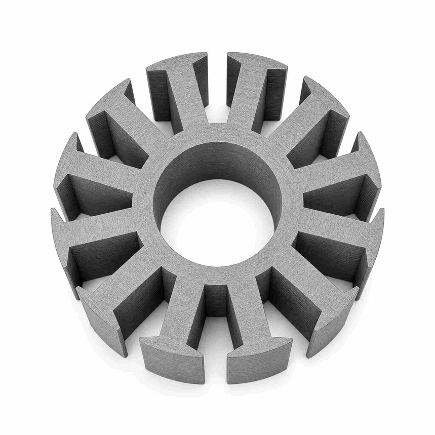
A radial motor core starts as a stack of thin electrical steel laminations. Each lamination carries a punched profile. Stacking those profiles builds the three-dimensional iron body that guides magnetic flux. The stator and the rotor use the same base material. Their shapes and their assembly methods set them apart.
Stator Core Geometry
The stator is a cylindrical iron core with slots cut into its inner bore. Those slots hold the copper windings that generate the magnetic field. A stamped lamination shows a ring of teeth pointing inward, and each gap between teeth becomes a slot once the stack is complete. The outer rim, called the yoke, carries flux from tooth to tooth around the circumference.
Builders stack stator laminations in one of several ways. Interlocking, welding, and adhesive bonding all produce a solid core. Shunge's Self Bonding Radial Stator Core uses a bonding coating on the lamination surface. The coating cures under heat and pressure and fuses the stack into a single rigid unit. This approach leaves the slot walls clean and keeps the tooth profile accurate. The bonded stack also reduces vibration between laminations during operation.
Rotor Core Geometry
The rotor is the inner part that spins on the shaft. It carries permanent magnets, and it sits inside the stator bore in most radial designs. Some outer-rotor topologies place the rotor around the stator instead. Either way, the rotor core provides the iron path behind the magnets and the mechanical structure that holds them in place.
Rotor geometry differs from stator geometry in one key respect. The rotor needs pockets, bridges, or surface features that retain the magnets against centrifugal force. Lamination stacking follows the same principle as the stator, but the bonding method must survive rotation. Shunge's Self Adhesive Lamination Radial Rotor Core applies adhesive between laminations during stacking. The cured bond holds the stack together without rivets or interlocking dimples that would distort the magnet pockets.
Both build approaches are valid fits for their own part. Self bonding suits the slotted stator profile. Self adhesive lamination suits the magnet-retaining rotor profile. Neither method is universally superior. Each one matches the geometry and the mechanical duty of the component it serves. Together they form the two halves of the Radial Motor Cores that drive a radial flux machine.
Magnetic Circuit Roles
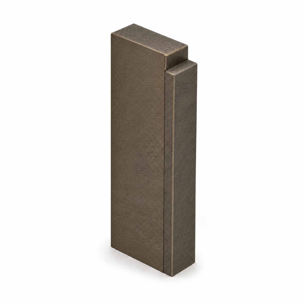
Stator Field Path
The magnetic circuit begins with the windings in the stator slots. Current in those windings produces a magnetic field. That field crosses the air gap and enters the rotor. The return path runs through the rotor iron, back across the gap, and into the stator teeth. From the teeth, flux travels along the yoke and around the circumference to complete the loop.
In a radial flux machine, the flux moves perpendicular to the shaft. It travels outward from the rotor pole, crosses the air gap, and enters the first stator tooth. This radial path is longer than the flux path in an axial machine. An axial design sends flux parallel to the shaft over a short axial length. A radial design sends flux across the full radial depth of the rotor and stator bodies. The longer path raises the reluctance of the circuit. Designers compensate with enough iron cross-section and a tight air gap.
The stationary stator completes the magnetic circuit. Its yoke closes the loop between adjacent teeth. Its laminated stack carries flux around the full circumference without interruption. Shunge's Self Bonding Radial Stator Core keeps that path stable. The bonded laminations act as one solid iron body, so flux crosses lamination boundaries with minimal disturbance. A loose stack would introduce gaps and raise losses along the same path.
Rotor Flux Interaction
The rotor does not generate the main field in most radial designs. Permanent magnets on the rotor provide the flux source. The rotor core shapes that flux and directs it toward the stator teeth. Each magnet pole pushes flux across the air gap. The stator then receives that flux and completes the circuit through its own iron.
The rotating rotor interacts with the field rather than merely carrying it. As the rotor turns, each pole aligns with a new set of stator teeth. The interaction between rotor flux and stator field produces torque. The quality of that interaction depends on the accuracy of both iron paths. A rotor with distorted magnet pockets weakens the flux pattern. A stator with rough slot walls disturbs the field in the gap.
Shunge's Self Adhesive Lamination Radial Rotor Core supports this interaction in a practical way. The adhesive bond holds each magnet pocket in shape during rotation. The stack stays true, so the flux pattern stays consistent from pole to pole. Both core types work as one magnetic system inside radial motor cores. The stator sets the path, and the rotor drives the flux through it. Neither part functions well without the other.
Performance Characteristics
Efficiency And Losses
Loss behavior differs between the two core types. The stator carries the main field around the full circumference. Its yoke and teeth see continuous alternating flux. Core loss in the stator therefore depends on the steel grade, the lamination thickness, and the quality of the interlamination bond. A bonded stack limits eddy currents between laminations and keeps those losses in check. Shunge's Self Bonding Radial Stator Core supports this behavior through its cured surface coating.
The rotor core handles a different loss profile. Its iron sits behind the magnets and shapes the pole flux. The longer radial flux path raises the reluctance of the whole circuit. That longer path affects both parts, not just one. Designers offset it with adequate iron cross-section and a tight air gap. The rotor also sees harmonics from the stator slotting, and those harmonics generate additional loss in the rotor iron. A rotor stack with a stable bond resists this effect. The Self Adhesive Lamination Radial Rotor Core keeps its laminations aligned, so the harmonic loss stays predictable.
Torque And Mechanical Demands
Torque quality depends on both iron paths. The stator field must align cleanly with the rotor poles. Slot geometry and tooth accuracy shape the torque ripple. A clean slot wall and a true stack reduce ripple and smooth the output. The rotor contributes through magnet placement. Accurate magnet pockets keep the flux pattern even from pole to pole. Both core types perform best when their geometry stays true under load.
The mechanical demands separate the two parts sharply. The stator stays still. It faces vibration and thermal cycling, but no centrifugal load. The rotor spins, so it must hold its magnets against centrifugal force at every speed. That duty makes bond strength and stack integrity critical in the rotor. The stator rewards accurate slot forming and a rigid bonded body. Each part meets the demand its own position creates. These roles define how Radial Motor Cores perform as a system.
Application Fit And Cost
Where Each Core Fits
Stator cores serve the field-generating outer structure of a radial machine. The slotted ring holds the windings that create the main field. Industrial pumps, fans, compressors, and traction motors all rely on this outer ring to carry flux around the circumference. A designer picks a stator core when the machine needs a strong stationary field path and clean slot geometry for the winding.
Rotor cores serve the rotating inner assembly. They carry the magnets and turn on the shaft. Servo drives, electric vehicle traction units, and spindle motors use this inner part to deliver torque across the air gap. An outer-rotor topology reverses the positions, yet the same logic holds. The rotating part still needs magnet retention and stack integrity at speed.
Cost And Compliance Drivers
Lamination grade sets the first cost driver. Thinner laminations and higher-grade steel raise material cost, and they also lower core loss. Bonding method adds the second driver. Self bonding and self adhesive lamination both remove interlocking dimples and rivets, and they replace them with a coated or glued stack. That step adds coating or adhesive cost, yet it cuts secondary operations and scrap. Tooling forms the third driver. Complex magnet pockets and fine slot profiles need precision dies, and die cost spreads across production volume.
Compliance considerations follow the same logic. Electrical steel grades must meet the magnetic and mechanical specifications the design names. Bonded stacks must hold their strength through thermal cycling and, on the rotor, through centrifugal load. Shunge supplies both self bonding radial stator cores and self adhesive lamination radial rotor cores, and the company documents each build against the agreed specification. Buyers can review product details at www.shungesteeltrade.com. These Radial Motor Cores share one material base, so the cost gap between them comes from geometry and bonding, not from steel alone.
The stator core stays still on the outside. The rotor core spins on the inside. That single fact shapes construction, magnetics, performance, and cost.
Neither core is universally better. Stator cores suit the field-generating outer structure. Rotor cores suit the rotating inner assembly. Selection should follow the design's priorities. Designers chasing smooth torque should focus on slot and magnet pocket accuracy. Efficiency goals point to steel grade and bond quality. High volume rewards precision tooling.
Shunge supplies both self bonding radial stator cores and self adhesive lamination radial rotor cores, so readers can match either part to their design. Radial Motor Cores will keep evolving toward tighter tolerances and stronger bonded stacks.
FAQ
How does a reader tell a stator core from a rotor core?
The stator core forms the stationary outer ring. It carries slots for the windings. The rotor core forms the rotating inner part. It holds the permanent magnets and turns on the shaft. Position and motion separate the two parts inside Radial Motor Cores.
Can a designer swap a stator core for a rotor core?
No. Each part serves its own position in the machine. A stator core needs slot geometry for windings. A rotor core needs magnet pockets and stack strength at speed. The two parts work as one magnetic system, and neither replaces the other.
Why does the radial flux path matter for core selection?
Flux crosses the air gap perpendicular to the shaft. That radial path runs longer than the flux path in an axial machine. The longer path raises circuit reluctance. Designers answer with adequate iron cross-section and a tight air gap in both core types.
How do the two bonding methods differ in practice?
Shunge's Self Bonding Radial Stator Core uses a surface coating that cures under heat and pressure. The Self Adhesive Lamination Radial Rotor Core applies adhesive between laminations during stacking. Both methods remove interlocking dimples and rivets. Each one matches the geometry and mechanical duty of its part.